Brachistochrone
Finding the fastest path from A to B
I got the idea for this model from a maths course I was taking on the calculus of variations. This is a slightly obscure branch of calculus that deals with finding paths which give minimum or maximum values of an integral containing an unknown function (this is called a functional).
The model illustrates the solution to a problem posed in 1696 by Mathematician Johann Bernouilli. This was to find the path that an object should follow in order to get from A to B in the shortest time possible moving just under gravity (and with no friction). It turns out that the curve to follow is called a cycloid; calculus of variation techniques allow the specific equation to be calculated. The easiest way to envisage a cycloid shape is to think of a bicycle wheel and imagine the path traced out by the valve, starting at ground level, as the wheel is rolled forward over level ground. Our cycloid is this shape but upside down.
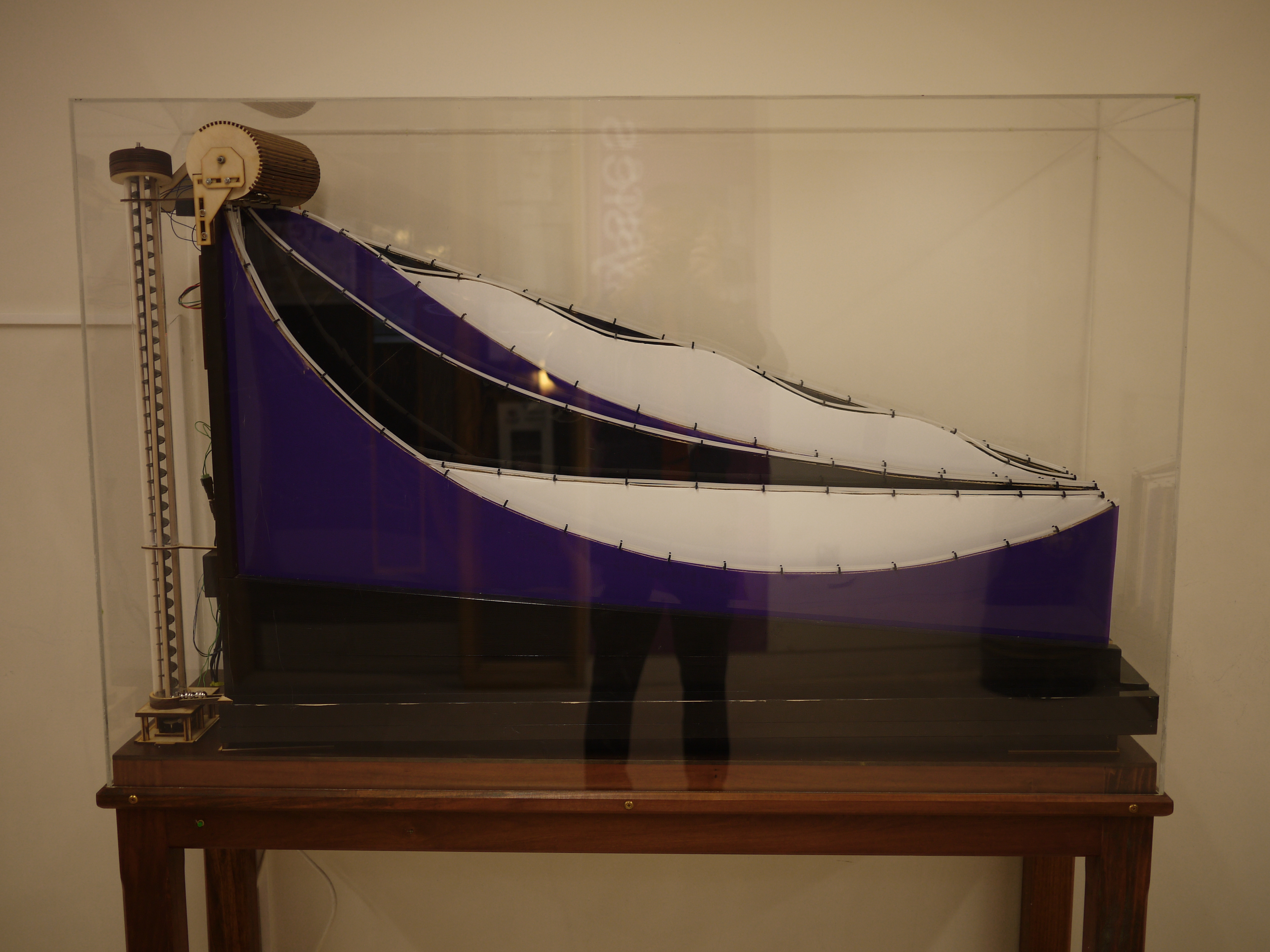
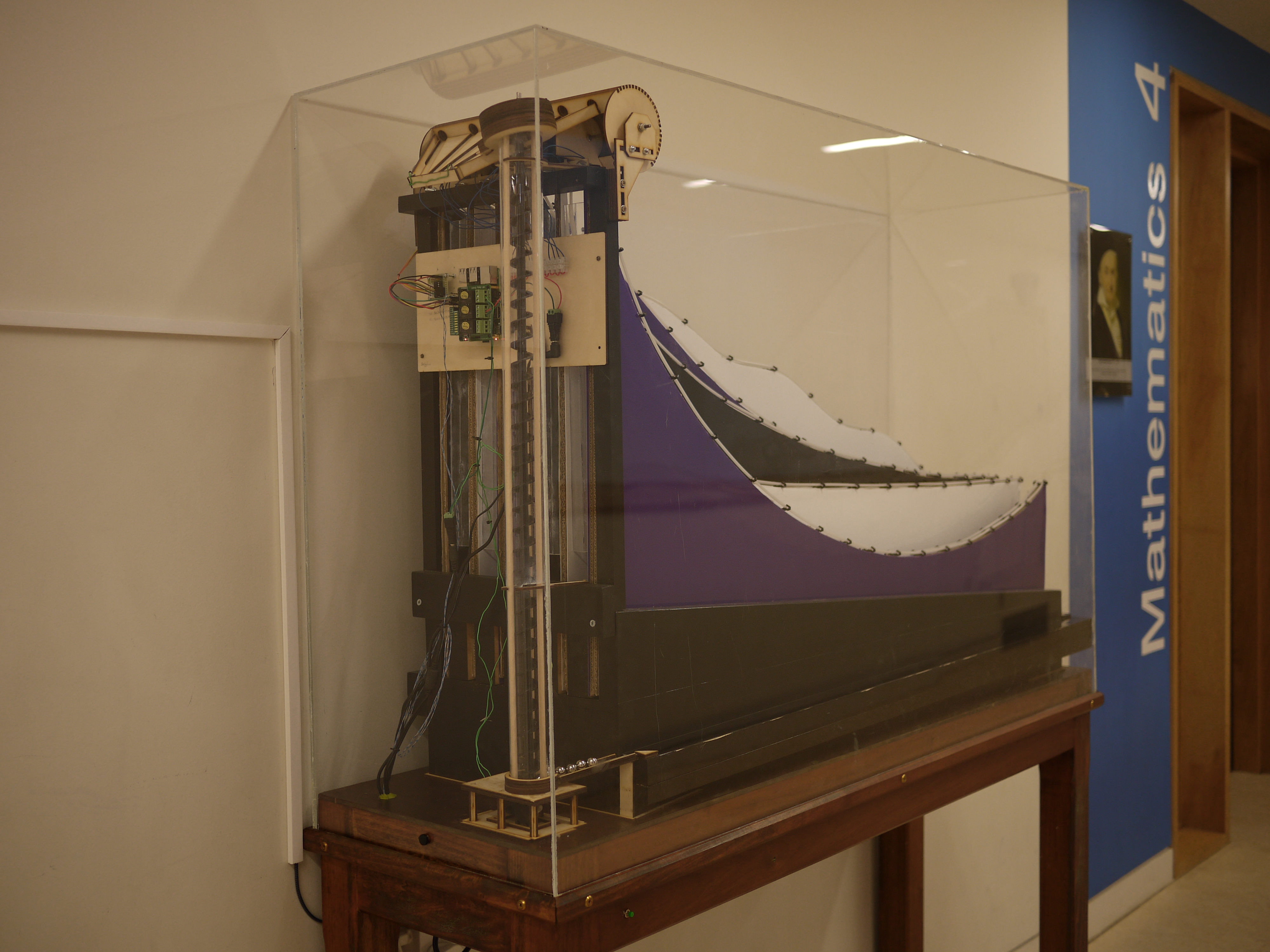
The model illustrates the cycloid’s supremacy by comparing six different paths all of which take a ball a vertical distance of 40cm and a horizontal distance of 120cm. The release mechanism is set up to start all the balls going at exactly the same time and it can be observed that the ball following the cycloid - the front curve - completes its journey first. In the physical model there are five different curves behind the cycloid, each taking a different time for the ball to traverse.
Interestingly, you may notice that the cycloid takes its ball on a path that goes below its end point for part of the journey - the ball is climbing when it reaches the end!
Model construction
The curves were made by Maths and Physics Sixth Form pupils at my school as part of their enrichment lessons. This involved drawing each curve in PowerPoint and projecting a full size image onto a whiteboard to sketch onto a piece of card, which was used as the template for other pieces of card and facing plastic to make the curve. To ensure balls roll smoothly and as friction free as possible, a piece of nylon rail from a SpaceRail (marble run) kit was hot-glued to the top of each curve.
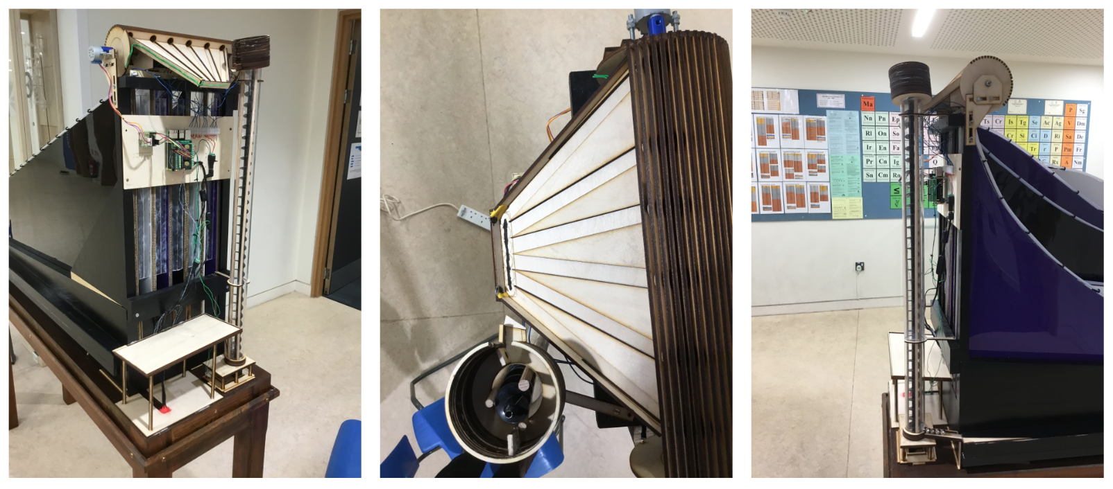
Making the mechanism for raising and simultaneously releasing the balls was quite a challenge. Electromagnets are used as the release mode since these can be made to consistently release at exactly the same time. This level of precision is needed because the difference in journey time between some paths is so small that simultaneous release is critical to be able to observe the effect. Getting the balls from the start point to the magnets involves an intricate mechanism, starting with an Archimedes screw lift that drops the balls into a tray attached to a cylinder which rotates to deliver each ball directly onto a magnet. The screw lift is turned off and the cylinder rotation sequence started once all balls are in the tray. When the balls are delivered to the magnets the cylinder rotates back out of their way and the magnets are turned off to release them. At the end of their curves the balls fall onto a series of sloped ramps which roll them around the edge of the case to the entry of the lift. The model is then primed for the process to repeat when a user presses the start button on the outside of the case. All of these actions are coordinated via a Rasberry Pi device.

To show that a wider variety of curves are 'beaten' by the cycloid I also developed a computer model, which is displayed on an iPad next to the display. This model allows users to vary all of the curves apart from the cycloid, which 'wins' regardless of how the other curves are configured. The model was developed in GeoGebra, a superb (and free) mathematical modelling language. It works by solving the differential equation of motion numerically for the curves as configured by the user, so motion on the iPad (excluding friction) is as would be observed in the real world. You can try out this model here
The maths behind the model
The maths behind the calculation of the cycloid equation used in the model is a bit involved, but I've written this out for anyone interested, it can be accessed here
With thanks to
Mike Reed, who built the electronics that control the mechanical parts, Cameron Holmes, who helped build the curves with assistance from pupils, Nick Small who built the case housing the model and Roy Curran for help with the DT laser cutter used for construction of many mechanical components.
