Pendulum Clock
This is another project with its origins in a maths course I was doing - this time non-linear ordinary differential equations.
The differential equation describing simple pendulum motion is fairly straightforward, or at least the commonly used approximation is, and forms part of some maths and physics A level courses.
A more sophisticated model where the pendulum is forced to keep moving e.g. by a weight regularly ‘kicking’ the pendulum (as in a pendulum clock) is rather more difficult to analyse, but has some fascinating features.
The key feature is that such a system forms a self regulating mechanism which produces periodic motion that can be turned into an accurate measurement of time.
The technical term is that the differential equation that describes the motion of a pendulum clock has a periodic (repeating cycle) solution called a ‘limit cycle’. Essentially, if one starts the pendulum swinging with an amplitude less than the limit cycle solution then the amplitude will automatically increase till at the limit cycle level and then remain there. Similarly if one begins the pendulum swinging with an amplitude above the limit cycle solution then the amplitude will automatically decrease to the limit cycle level and remain there.
This is the feature that allows a pendulum clock to be a reliable time keeper. In essence the regular kicks given to the pendulum rod via the escape mechanism are automatically kept to the limit cycle amplitude of the mechanism, and the regular period of the pendulum is converted via gears to drive the clock hands.
The maths of a pendulum being driven by a weight is complex, however just considering a simple pendulum (no regular kick from the weight) is easier. To see this click here
THE PROJECT
I was keen to try to build a clock in order to actually see this limit cycle solution in action and thought it would be a great project for Maths and Physics pupils to do. Not only is there lots of maths to discuss in modelling various forms of pendulum motion, but also the challenge and satisfaction of building an accurate time keeping device.We started the year with this objective but absolutely no idea how we were going to achieve it.
ATTEMPT 1
Our initial attempt was to try and build a pretty basic weight driven pendulum following instructions based on a physics website. This only ran for about 30 seconds and was quite ‘lumpy’ due to the unsophisticated design and fairly irregular shapes of the gears which we cut ourselves. It was clear more precision was needed.ATTEMPT 2
We found an intriguing book that purported to contain templates for all the pieces needed to build a weight driven pendulum clock out of its cardboard pages! While this seemed a great idea with much potential, after lots of effort it was clear that the level of accuracy and attention to detail necessary to get a good result were significant. Between several classes we got a reasonable version pieced together and the principles by which the clock should work were clear, but our failure to cut the pieces absolutely accurately had a big impact on the free running of the mechanism. Basically it looked quite good but didn’t work well!ATTEMPT 3
After more research we found a template for a clock that could be cut from a single piece of 4mm plywood and slotted together. This was the result of a project between a clock maker and Loughborough University which aimed to provide an easy method of building an accurate weight driven pendulum clock. Exactly what we were trying to do.All that was needed was a laser cutter, which fortunately my school has.
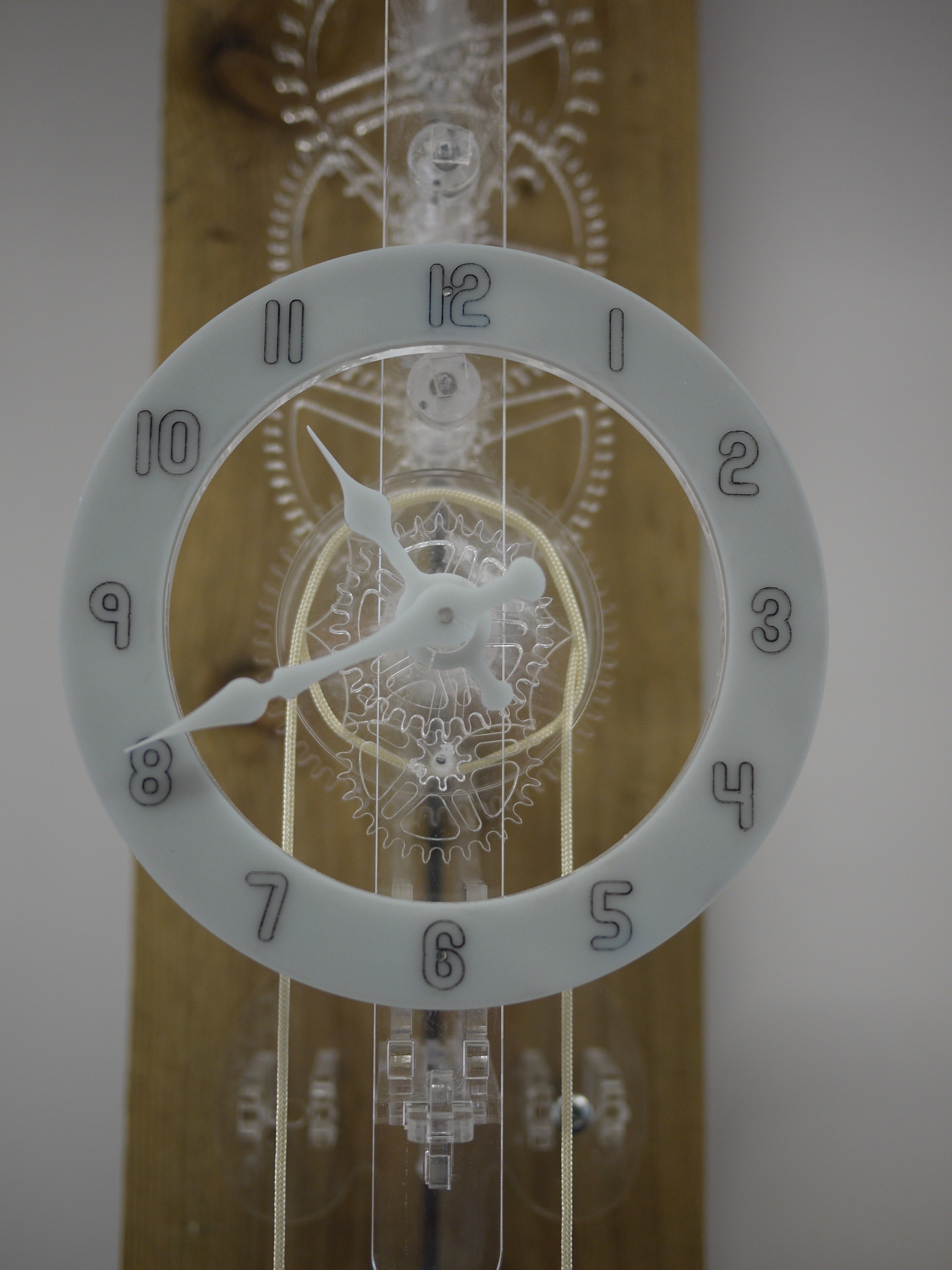
To make the clock more appealing we decided to use clear acrylic for the pieces rather than wood. This worked well, and the clock produced is pictured in the menu item you followed to get to this page.
With the clock fixed at 5 feet 6 inches above the ground raising the weight to clock face level gives about 8 hours of running time. Amazingly it is accurate to within a minute or two over this period.
Most impressively the clock does allow the limit cycle behaviour as described at the start of this page to be seen in action.
In real terms what the limit cycle solution represents is a balance between the friction in the mechanism and the potential energy of the weight. Increasing the weight would result in a different limit cycle solution, with the pendulum amplitude increasing a little. The timekeeping of the clock would be unaffected since the period of the pendulum is (almost) independent of its amplitude for small maximum angles of displacement from the vertical.